Arduino Exposure Meter
Concept
As everyone knows, exposure is an integral part of photography. The first exposure meter was found on the Kodak Super Six-20 in the late 1930's, and became increasingly commonplace in the 1960's, when TTL metering and other advanced techniques were introduced. So why go about reinventing the wheel? Certainly there many (too many to list, in fact) exposure meters available to purchase, new and used. The first reason is this: to my knowledge, no commercially available light meter is "hackable." Want to add some crazy f-stops for a pinhole camera? If you can, you'll have to kludge it. Want to use it to report exposure values to a PC or other device? Too bad. As is the case with most things, if you want it done your way, you'd better do it yourself. Reason number two: developing a light meter provides some insight into photometry and exposure calculations that would be useful in, say, integrating a TTL meter into a camera one day. Reason three: you can git-r-dun for cheap. About $45 in this case. Reason four: because we can - so why not???
Materials
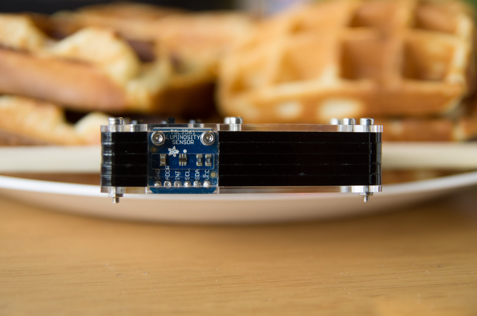
I wanted this light meter to be at least two things: small, and usable. I don't expect Voigtlander VC - scale levels of compactness, but a pocket-sized device was preferred. In terms of usability, I expected a high dynamic range (measurements can be taken in very bright and very dim light), easy-to-read display, and simple operation.Photoreceptor: Adafruit TSL2561 Breakout
This is the heart and soul of the exposure meter. This is not a light-dependent resistor, instead it is a light-to-frequency converter which has a bunch of snazzy features. It's an integrating luminosity sensor, which means that it can output illuminance (lux) readings over a very large range of input light (0.003 to 65000 lux, or so says the TAOS datasheet) using variable gain and integration times, and visible light and(!) UV light photoreceptors. Adafruit packaged this sweet, sweet goodness into a simple breakout board with I2C interface and a simple library. The library provided doesn't provide sub 1-lux resolution, however. I think that could be fixed by making some tweaks to the library.Display: Adafruit 128x32 0.96" OLED
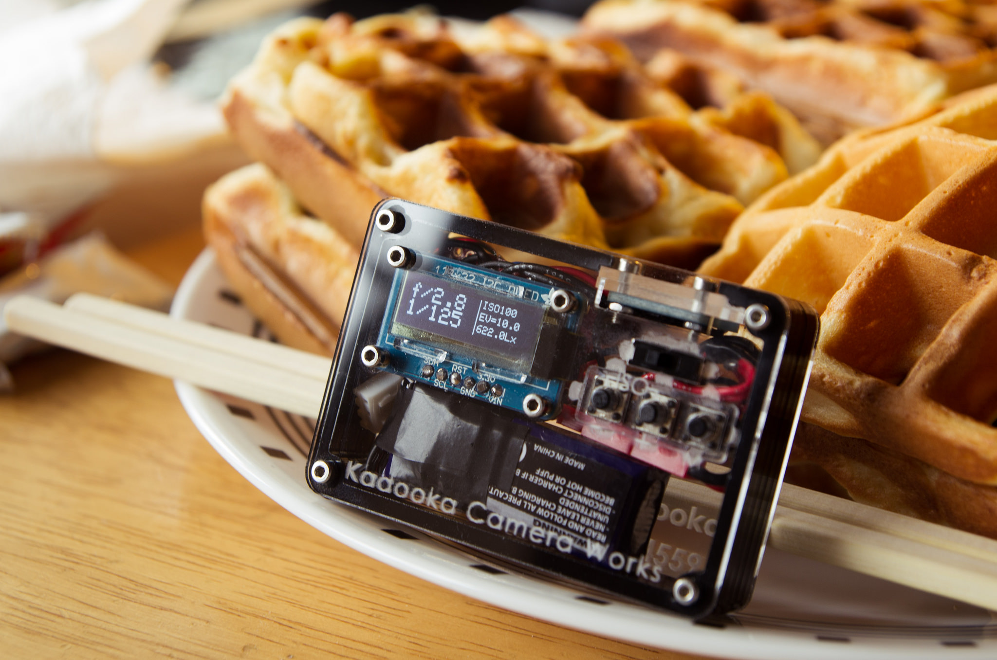
Another really cool piece of work from Adafruit. This one's a little pricey at about $18, but the sharpness and contrast of the display make it worth it. I can fit aperture, shutter speed, ISO, EV, and Lux values on the screen at the same time - YMMV, depending on your visual acuity. Also, the accompanying Adafruit GFX and SSD libraries are really easy to work with, even for an ME bonehead like me.Microcontroller: Sparkfun Pro Micro (5V)
Yes, I know I should have used a 3.3V microcontroller, and a 1s LiPo to save power and weight! But I do most of my work in the 5V domain, so I'm okay with losing a little space to an extra battery cell. So sue me. But here I'm using the Pro Micro, with a ATmega32U4, instead of a Trinket or other ATtiny device because of the extra I/O's, and because driving the OLED's requires some smarts.Power: Turnigy 2s1p 300mAh Lithium Polymer (7.2V)
These are really cute little LiPo cells. They're really tiny, at just 44x17x12mm (about the size of AA battery - that's some power density). Not much to say here, other than that they'll provide pretty good battery life (upwards of 10 hours, if my back-of-the-envelope calculations are to be believed) and won't take up too much space in the enclosure.Housing: Laser-cut Acrylic
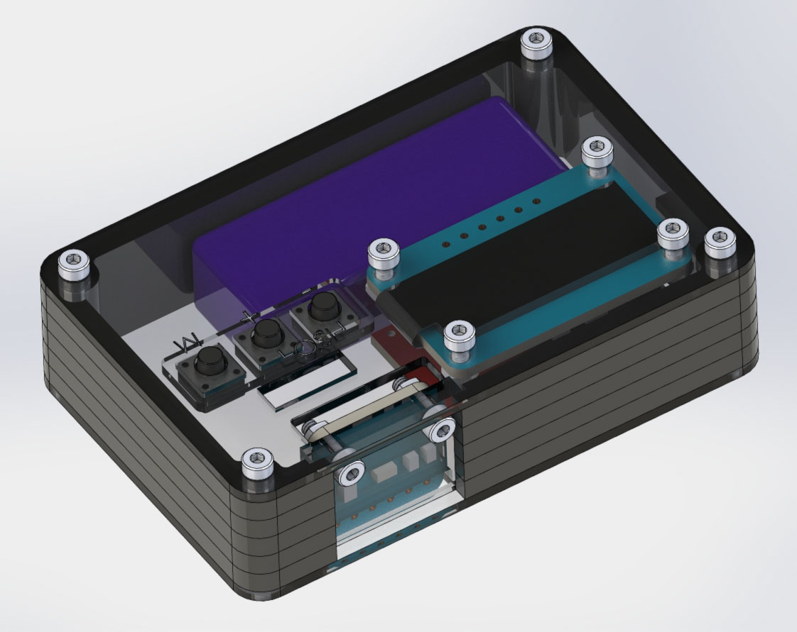
Sure, I could have gone 3D printed, but laser-cut acrylic seems so fitting for a sleek little device. I got a timber-themed Pibow for my Raspberry Pi (which this webpage is hosted on, no less), and really dug the flat-pack design.Other Materials
Aside from the above parts, I also used some M2 nuts and bolts to hold it all together (4x 20mm, 6x 8mm). You can get these from McMaster Carr. For the buttons, I used 3x 6mm x 6mm x 7mm (tall) tactile buttons. For a power switch, I used Adafruit's breadboard power switch.Circuit
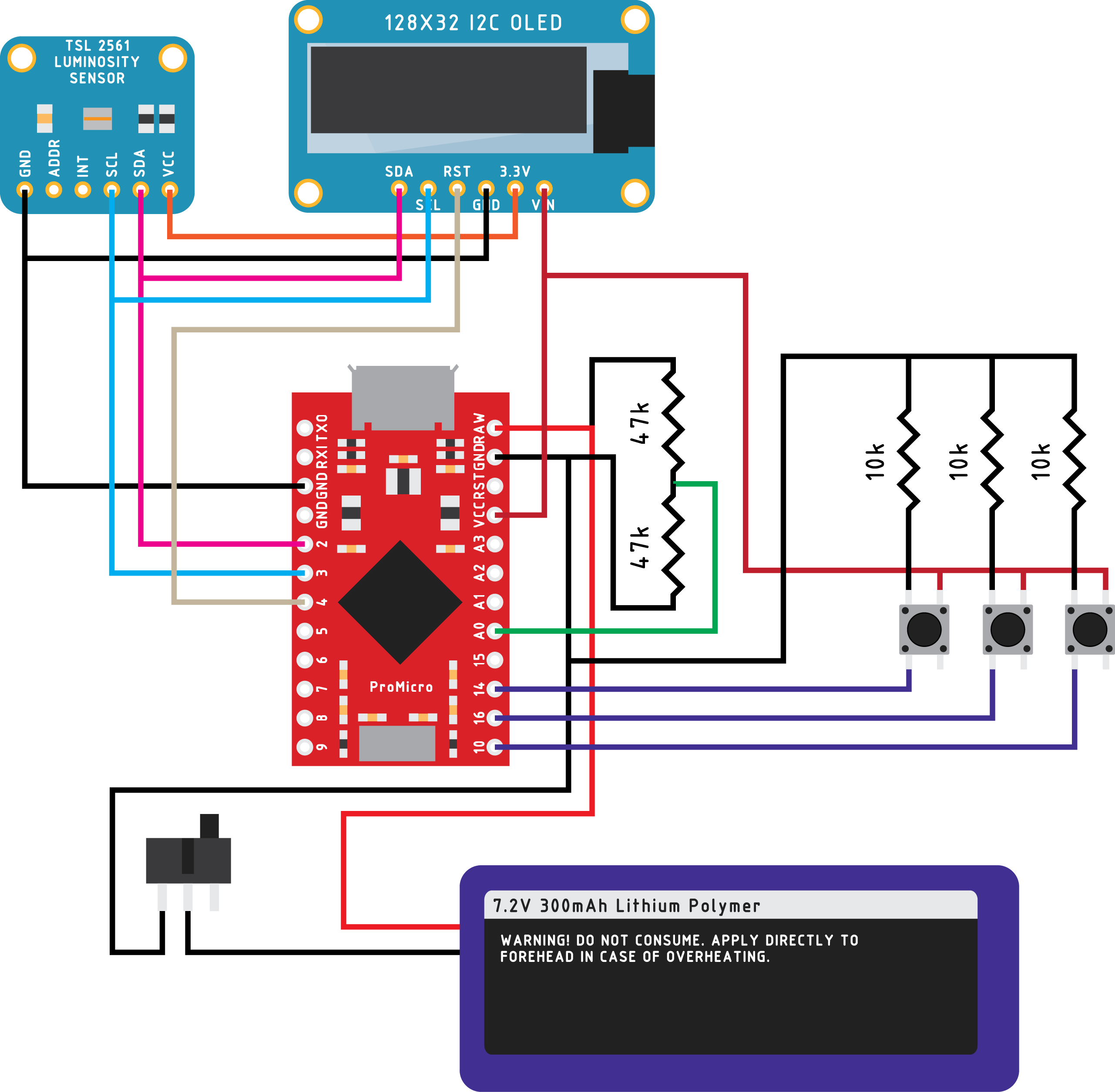
Code
You can get the Arduino code HERE.Please note that you also need a couple of Arduino libraries for it to compile properly. You need:
Housing Files
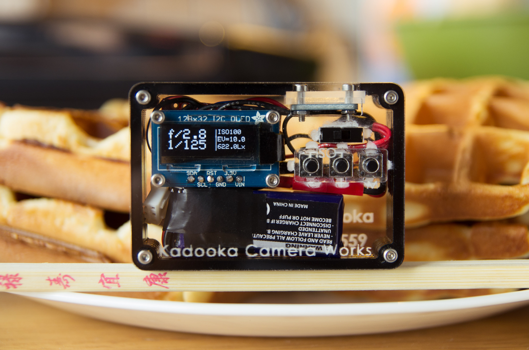
Here are the the CUT FILES for the housing. I used 1.5mm and 3mm laser-cut acrylic, and you may need to make some modifications for whatever parts you choose to use.Photos
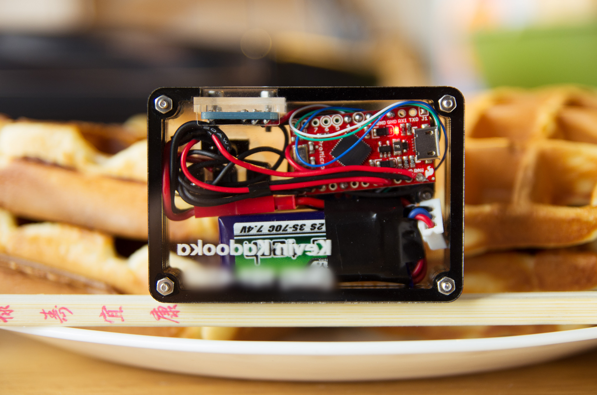
Thoughts
It's definitely not perfect, but I'm pleased with how it turned out. It is sleek and pretty tiny - just 72 x 50 x 18mm. Just for comparison, a credit card has a 86mm x 54mm footprint! You can keep it ready in your pocket or throw it in your camera bag without taking up any space at all. It is also really easy to use and the display is very clear except under the strongest of sunlight (and in that case, just use Sunny 16!). It could be prettier, but the laser cut acrylic keeps it in a tidy, durable (I hope, at least), and inexpensive package. I really think this project is one that anybody can do, provided basic soldering skills and the ability to copy and paste. I'd be really excited to see if others pick up this project!A couple of things I would improve in the future: